The Artwork Fits but the Cut Boundary Does Not
An empirical review of bounding box illusions, vector cutline offset physics, and edge collisions when print margins ignore cutter travel.
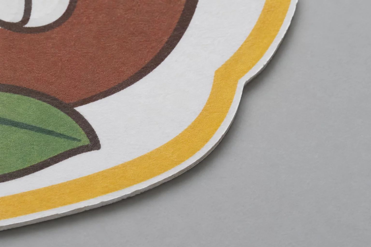
Why Bounding Box Clearance Conceals Cut Failure
Desktop software frequently reports that an illustration sits comfortably within printable sheet margins, yet the physical blade slices straight into registration lines or sheet edges. This issue stems from the software calculating visual dimensions from rectangular bounding boxes rather than tracking the outermost coordinates of vector cutting paths.
During our test runs on standard matte vinyl, the graphic appeared centered with 4.5 mm of apparent side clearance. However, when generating an outer contour offset of 2.5 mm, outward path expansion pushed cut nodes into the optical sensor clearance band. The blade followed the vector path rather than the visual frame, colliding with mechanical carriage limits before the cut completed.
Inspecting Cutlines in Silhouette Studio
Learn how to inspect vector nodes, toggle mechanical cut previews, and verify clearance margins prior to printing.
Vector Clearance vs Physical Tool Travel
| Parameter | Observed Vector Coordinate | Physical Trim Result |
|---|---|---|
| Graphic Outer Bounds | 68.20 mm × 68.20 mm | Fits Print Area |
| Generated Cutline Offset | +2.50 mm (73.20 mm span) | Exceeds Safe Trim |
| Sensor Clearance Zone | 5.00 mm from Grid Tab | 1.80 mm Intrusion |
| Bottom Roller Margin | 12.70 mm Sheet Edge | Carriage Slip |
| Effective Boundary Shift | ΔX: +0.85 mm / ΔY: -1.10 mm | Perimeter Clipped |
Node Expansion Mechanics on Asymmetric Artwork
Graphic software suites calculate artwork boundaries using axis-aligned orthogonal rectangles. When an illustration features irregular contours, sharp curves, or organic extensions, the visual margin inside the layout box looks deceptively generous. The cutting engine does not recognize rectangular bounds; it parses only discrete Bézier curves and mathematical vertex positions.
Applying an offset tool pushes each vertex outward along its normal angle. In acute convex corners, offset vectors create elongated miters that extend significantly farther than the requested distance. When placed near registration mark exclusion zones, these extended nodes cross directly over optical sensor travel corridors, confusing registration optics or running off the blade cutting path.
- Measure margins from the outermost offset vertex rather than the raster bounding box.
- Maintain at least 3.5 mm of empty media between vector cutlines and registration mark zones.
- Convert mitered corners to smooth rounded offset paths to avoid unexpected node projection.
Correcting this problem requires evaluating toolpaths independently from printed graphics. By disabling visual raster guides and reviewing the absolute position of the cut path against registration borders, designers prevent blade clipping and material waste before producing full production sheets.
A graphic can comfortably satisfy every print margin on your canvas while its expanded vector cutline breaches physical mechanical tolerances by several millimeters.
Boundary Clipping Inquiries
Most design platforms isolate the print raster layer from the cut line path. Because the print job itself complies with sheet bounds, the software renders the canvas as valid, ignoring vector path intrusion into optical sensor zones until job execution.
Mitered offset calculations project sharp angles outward until intersections meet. For acute angles under 45 degrees, this adds up to 40 percent extra length compared to a smooth rounded offset, easily encroaching upon margin boundaries.
Enable the cut preview mode with registration grid boundaries turned on. Verify that no red or cyan vector nodes fall within 3.5 mm of either registration marks or physical sheet edges.