Twelve Stickers, One Inconsistent Margin
How an unexpanded stroke setting on a solitary cloned badge generated a 0.72 mm offset variance across an otherwise flawless 3x4 gang sheet.
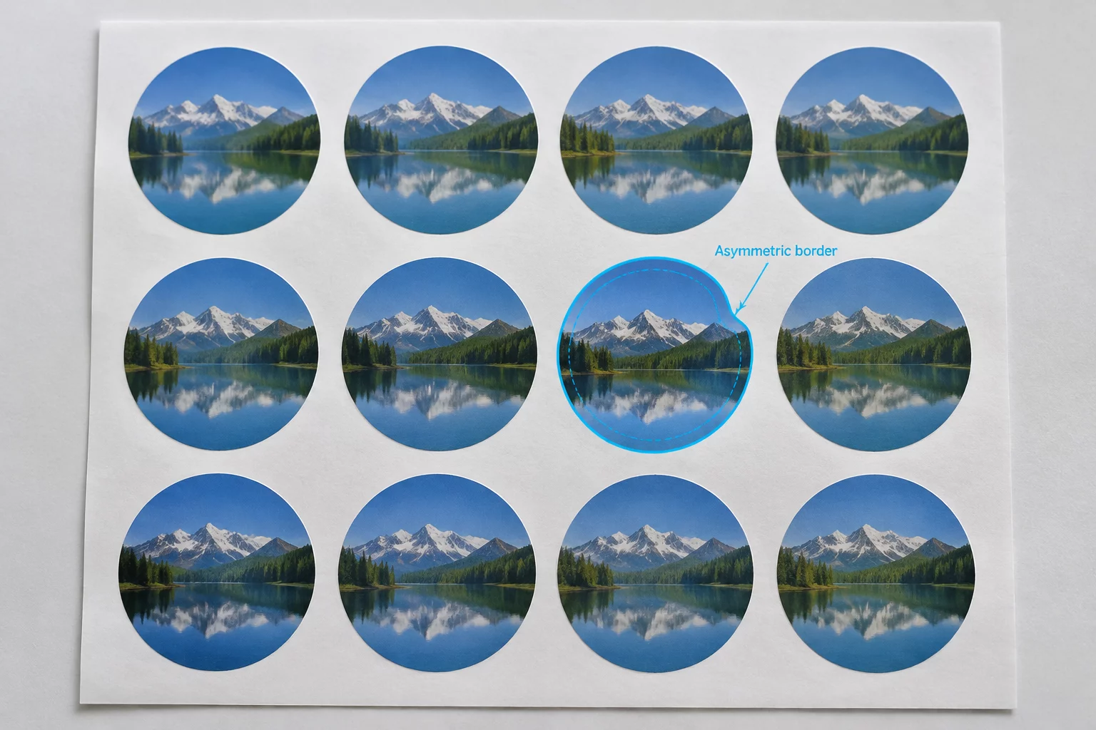
Uniform Arrays Harboring Asymmetric Flaws
A twelve-up gang sheet produced on standard self-adhesive vinyl appeared perfectly balanced on screen, displaying an intended white border of exactly 1.50 millimeters around every printed badge. When the mechanical blade completed the job, eleven stickers peeled off with clean, symmetrical borders, but the seventh badge exhibited an uncharacteristic top-left trim erosion.
Most designers assume that using the software duplicate matrix guarantees geometric parity across every row and column. In this specimen, eleven instances retained their grouped internal paths and uniform offset tolerances, whereas the badge resting at row three, column one underwent an accidental manual nudging before cut lines were compiled into the final send queue.
Multi-Up Grid Repetition Rules
Check our spacing reference manual to prevent unlinked offset anomalies on gang layouts.
Per-Badge Boundary Metrics
| Parameter | Observed Vector Coordinate | Physical Trim Result |
|---|---|---|
| Badges 1 through 6 Offset Margins | Uniform +1.50 mm external vector stroke | Balanced Border |
| Badge 7 Outer Trim Clearance | Shifted -0.78 mm north-west (0.72 mm visible) | Asymmetric Thin Edge |
| Badges 8 through 12 Offset Margins | Uniform +1.50 mm external vector stroke | Balanced Border |
| Sheet Registration Sensor Check | Front optical read deviation < 0.05 mm | Accurate Feed |
| Carrier Mat Deflection Factor | Lateral roller slip < 0.02 mm across Y-axis | Zero Feed Skew |
Decoupled Cutlines Inside Replicated Groups
Optical microscope inspection under directional 5000K lighting ruled out hardware slip. The carriage roller tracking remained linear, and registration marks registered with zero rotational error. The discrepancy belonged strictly to the digital vector file prior to spooling.
Upon breaking down the document layer tree, we discovered that badge number seven had its vector outline detached from the artwork bounding box during a manual alignment check. While the other eleven stickers were locked compound paths, this specific item received an unintentional two-point arrow nudge, displacing the red cutline while leaving the underlying CMYK artwork undisturbed.
- Lock grouped artwork and offset cutlines together before initiating any array replication command.
- Run a global layer audit using wireframe preview to confirm zero deviation across all duplicate contours.
- Verify that cut boundaries are designated on a single dedicated locked layer prior to sending output to the plotter.
When working with dense multi-up sheets, small keyboard nudges can ruin an entire production tier without being spotted on standard zoom levels. A rapid outline check in software remains the fastest line of defense against single-item offset flaws.
Hardware drift affects entire columns or causes gradual diagonal drift across the sheet. An isolated defect in just one badge almost always points to an unlinked vector path inside the software artboard.
Diagnosing Isolated Layout Errors
Mechanical drift accumulates progressively from top to bottom or across the carriage axis, worsening as the sheet advances. If an anomaly touches only one sticker while surrounding items remain accurate, the discrepancy is digital and isolated to that path.
When objects are ungrouped, individual vector sub-paths can respond independently to selection clicks, bounding-box recalibration, or slight cursor drag. Keeping cutlines on a separate dedicated layer prevents accidental partial selection.
Switching to raw Outline or Wireframe mode removes fills and effects, allowing you to clearly see the spatial distance between the graphic bounding line and the outer vector cut contour across every repeated instance.