The Printed Shape and the Cut Shape Are Not the Same Object
Investigating how automatic vector tracing, stroke expansion settings, and anti-aliasing feathering yield two distinct geometric shapes in one layout.
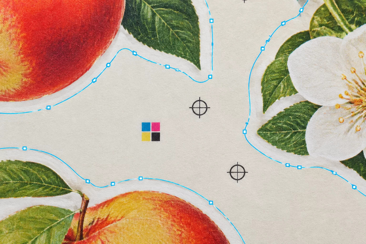
Independent Geometry Trapped in a Single Design Frame
A common pre-press assumption treats the vector cutting stroke as an exact outline clone of the visible graphic layer. When inspecting sample batch 44B under high magnification, the printed visual edge and the mechanical cutline turned out to be completely separate geometric entities possessing mismatched curves, unequal corner radii, and opposing center anchors.
This separation occurs whenever a design file introduces raster anti-aliasing during export or applies an automated silhouette trace tool without manual anchor point cleanup. The printer interprets pixel alpha blends as soft transitions, depositing color droplets right up to the 50% opacity threshold. Meanwhile, the cutting plotter software constructs Bezier curves through simplified node reduction, trimming across sharp corners where the print carries round fillets. Instead of following the visual graphic, the blade carves out its own distinct polygon.
Inspect Cut Paths Before Running Production
Learn how to verify node coordinate alignment against raster pixel boundaries in our dedicated Silhouette Studio review guide.
Boundary Coordinate Differences Recorded in Lab Testing
| Parameter | Observed Vector Coordinate | Physical Trim Result |
|---|---|---|
| Corner Radius Treatment | R = 0.40 mm sharp tangent vector | Clipped Ink Corner |
| Center Mass Displacement | ΔX +0.38 mm / ΔY -0.22 mm | Asymmetric Border |
| Anti-Aliasing Fringing Area | 1.2 px alpha gradient at 300 DPI | Unintended Halo |
| Node Count Discrepancy | 8 nodes (cutline) vs 14 nodes (print) | Segment Distortion |
| Compound Path Interior Aperture | Offset +0.65 mm inward constriction | Inner Edge Shave |
Why Offset Outlines Fail to Mirror Source Raster Contours
When artwork creators place a high-resolution PNG on the digital mat and click the automated tracing button, the software engine attempts to identify an edge by testing contrast thresholds. High contrast detects dark pixels readily, but intermediate semi-transparent pixels create a stair-stepped jagged boundary. The software applies a smoothing algorithm to suppress these steps, generating Bezier curves that cut across the intended visual crests.
Adding an outward offset creates secondary geometric complications. Instead of creating an equidistant envelope, miter limits and bevel joins alter sharp apexes into blunt tabs. As a result, the cut path no longer shares identical symmetry with the visual print below it, causing physical die-cut blanks to look crooked despite perfect machine optical mark alignment.
- Extract native vector paths directly from the master vector artwork rather than re-tracing flattened raster exports.
- Align the bounding box center points using numerical coordinate values instead of relying on optical group centering tools.
- Standardize all corner join styles to round joins when generating outward bleed or inset cutlines.
Pre-flight routines must treat cutlines and print graphics as two paired components of a compound assembly. Testing node coordinates against the master artwork in wireframe view guarantees that the blade cuts the exact polygon the designer intended to showcase.
The cutter does not see your artwork colors or drop shadows; it only follows mathematical coordinate vectors. If your cut line was calculated using automatic raster tracing, it is already a different object from your graphic.
Frequently Asked Questions
Auto-trace interprets edge pixels through luminance thresholds. When anti-aliased pixels create transitional shades along curved silhouettes, the tracing engine draws vector anchors through an averaged boundary path rather than tracing exact outer visible contours.
Switch your design workspace to wireframe view or set the cutline stroke to a high-contrast 0.25 pt red line with 50% fill opacity. Zooming in past 300% will reveal any discrepancies between graphic silhouettes and cut boundaries.
No. Registration marks align overall sheet coordinates. They cannot fix local vector distortion, mismatched node radiuses, or shape asymmetries caused by improper cut path geometry.