Multi-Up Alignment Drift Across Long Sheets
Analyzing mechanical feed slip and optical mark triangulation decay across 24-inch gang runs.
Why Identical Duplicates Shift Progressively Down the Sheet
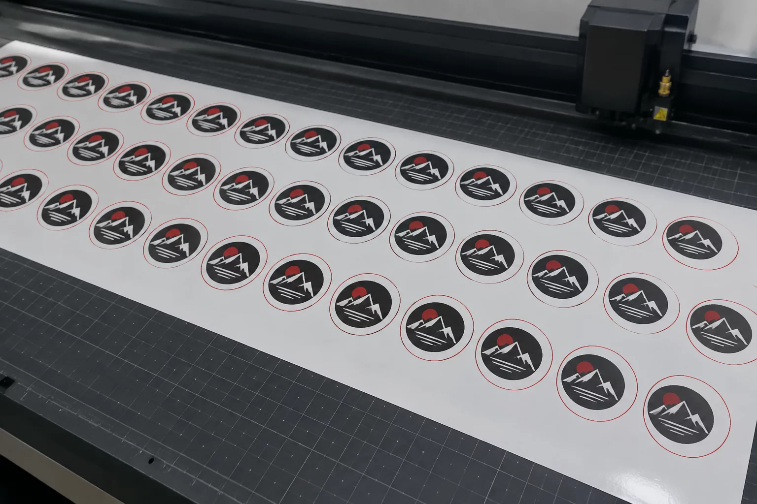
When replicating repeated die-cut badges or sticker units across extended material spans, digital previews promise flawless geometric consistency. However, physical traction behaves dynamically. As roller feed cycles accumulate tiny slip increments, each successive row drifts further away from its intended vector cutline.
In our controlled inspection of a twelve-row gang layout on 600 mm synthetic poly film, the top cluster aligned within a precise 0.15 mm margin. By the ninth row, registration mark compensation decayed, pushing horizontal trim boundaries 1.35 mm into graphic live matter.
Review Gang Spacing Standards
Examine mathematical spacing recommendations for multi-up stepped jobs before sending files to cut.
Coordinate Verification Across Feed Axis
| Parameter | Observed Vector Coordinate | Physical Trim Result |
|---|---|---|
| Row 1 Lead Cluster | Y: 35.00 mm (Offset: +0.08 mm) | Nominal Inset |
| Row 4 Intermediate Step | Y: 182.40 mm (Offset: +0.32 mm) | Acceptable Margin |
| Row 7 Center Transition | Y: 329.80 mm (Offset: +0.76 mm) | Noticeable Creep |
| Row 10 Lower Trajectory | Y: 477.20 mm (Offset: +1.18 mm) | Border Intrusion |
| Row 12 Tail Cluster | Y: 575.50 mm (Offset: +1.42 mm) | Severe Offset Clipped |
Feed Roller Micro-Slip and Sensor Geometric Distortion
The presumption that optical registration marks at the sheet corners create a rigid Cartesian plane fails across long spans. Material stretch, thermal printer expansion, and drive roller micro-slippage introduce non-linear distortion. Standard optical readers capture corner registrations upon entry, establishing transformation matrices that do not recalculate as the tail of a long media sheet oscillates.
When cutting heavy coated stocks without intermediate alignment registers, drag tension against the rear feeder roll produces cumulative downstream error. The blade assembly follows absolute vector commands, yet the physical substrate lags incrementally behind mechanical expectations.
- Intermediate segment registration marks reduce cumulative feed elongation errors across runs exceeding 300 mm.
- Symmetric grit roller pressure distribution prevents lateral angular skew during rapid forward-reverse cycling.
- Expanded outer bleed corridors prevent visible white crescent slivers on bottom-tier gang rows.
To verify sheet stability without sacrificing media, isolating test cutlines along the center spine reveals whether drift originates from linear feed stretching or diagonal traction skewing.
Registration is not a static stamp applied once at sheet origin; on long runs, every millimeter traveled tests roller traction and mechanical tolerance.
Clarifications on Sheet Length & Creep
Higher blade velocity elevates lateral drag and inertia during direction changes. This amplifies micro-slip on rubber grit pinch wheels, particularly when cutting thick vinyl or laminates along the longitudinal axis.
Dividing long sheets into segmented blocks with intermediate marks resets the coordinate origin every 150 to 200 mm. This effectively isolates drift to individual segments instead of compounding across the entire run.
Lead rows stay close to the initial calibration marks and benefit from maximum media contact with feed rollers. As the sheet feeds forward, loose tail overhang reduces drag resistance and shifts the traction balance.