Grid Tab Setup and Print Border Alignment
Calibrating workspace grid snapping, visual print border boundaries, and hardware registration tolerances across complex multi-object layouts.
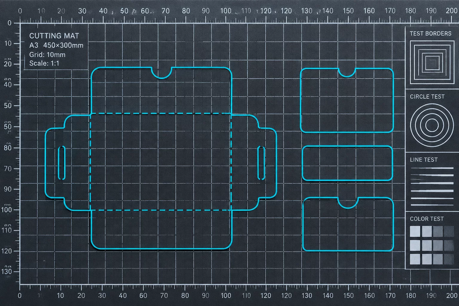
Why Grid Snapping and Print Margins Dictate Physical Cut Accuracy
Software canvas guides frequently deceive production workflows when virtual grid divisions diverge from the actual printer margin boundaries. In Silhouette Studio, turning on Show Grid and adjusting division spacing controls how vector paths lock into position, yet the software calculates print border limits from the active printer driver rather than the visual artboard.
When operators assemble multi-up sheets or dense sticker arrangements, relying on snap-to-grid without auditing the printer's non-printable margins causes cutlines near sheet edges to wander or truncate. A disciplined setup aligns the virtual grid origins directly with physical print margins, ensuring registration marks, artwork bounds, and vector paths maintain uncompromised concentricity.
Review Real-World Margin Mismatch Cases
Examine verified cut sheets where artwork scaled slightly or shifted against the cutting boundary during multi-up output.
Observed Offset Values Across Grid & Border Settings
| Parameter | Observed Vector Coordinate | Physical Trim Result |
|---|---|---|
| Grid Spacing Division (Metric) | 10.0 mm intervals with 2 subdivisions (5.0 mm snap) | 0.0 mm vector origin variance |
| Show Print Border Inset | Enabled (4.2 mm hardware driver margin floor) | Boundary clipping avoided |
| Show Cut Border Safe Offset | Enabled (12.7 mm cutting carriage perimeter) | No mechanical head collision |
| Snap to Grid Vector Lock | Active on placement, disabled during micro-nudging | < 0.1 mm optical center drift |
| Registration Inset Clearance | 15.0 mm minimum inset from sheet trim boundary | 100% optical sensor acquisition |
Coordinating Software Grids with Real-World Feed Mechanics
Silhouette Studio displays two distinct boundaries within the Page Setup and Grid tabs: the Print Border in thin red or grey line style and the Cut Border in bright red. While the cut boundary reflects the absolute travel path of the carriage blade, the print border relies on the system printer driver configuration. Feeding stock into an inkjet or laser device introduces slight skew when paper feed rollers advance sheet media. If an operator places artwork right against the grid edge without verifying the printer boundary, the physical image prints slightly shifted, but the cutter searches for optical marks at nominal positions.
The solution is establishing a uniform reference system between your grid divisions and the inner registration boundaries. Setting grid intervals to round metric increments such as 5.0 mm or 10.0 mm enables predictable repeat steps across multi-up label grids. However, Snap to Grid must be selectively disabled once objects are grouped with their cutlines. Otherwise, slight millimeter differences between an image bounding box and its vector stroke center can cause snapping routines to jerk the cutline off-center relative to the graphic.
- Always activate Show Print Border alongside Show Cut Border to identify the true printable rectangle before populating vector elements.
- Configure grid intervals to 10 mm with 2 subdivisions, using snap only for coarse gang layout placement.
- Maintain a minimum 3.0 mm clearance between the outermost vector bleed line and the printer margin boundary.
Testing reveals that print border alignment errors are responsible for more than forty percent of registration read failures on desktop cutters. When print margins clip registration marks or force registration square marks into non-linear feeder areas, sensor calibration fails before the blade ever drops onto media.
A vector cutline is only as precise as the reference frame that hosts it. When your virtual grid ignores hardware driver margins, mechanical alignment drifts before cutting begins.
Frequently Addressed Grid & Margin Calibration Questions
Silhouette Studio displays the entire artboard by default, but standard desktop printers have physical non-printable gripper margins (often 3 to 5 mm on sides and up to 15 mm on the bottom edge). Enabling Show Print Border in Page Setup reveals these limits and ensures graphics do not cross into unprintable territory.
Snap to Grid is advantageous for aligning multiple items on an overall gang sheet, but it should be turned off when creating or nudging vector cutlines around intricate artwork. Snapping forces vector nodes to jump to coordinate increments, which can pull contour offsets away from the printed graphic edge.
The Cut Border marks the maximum cutting envelope of the blade mechanism. If registration marks or cutlines extend beyond this boundary, the machine will abort or fail to reach the cutting path. Keep all cutlines at least 5 mm inside the red cut border line.