Bleed Extension vs Visible Margin Boundaries
Differentiating artwork over-extension from safe readable visual margins to prevent white flash and clipped edge graphics.
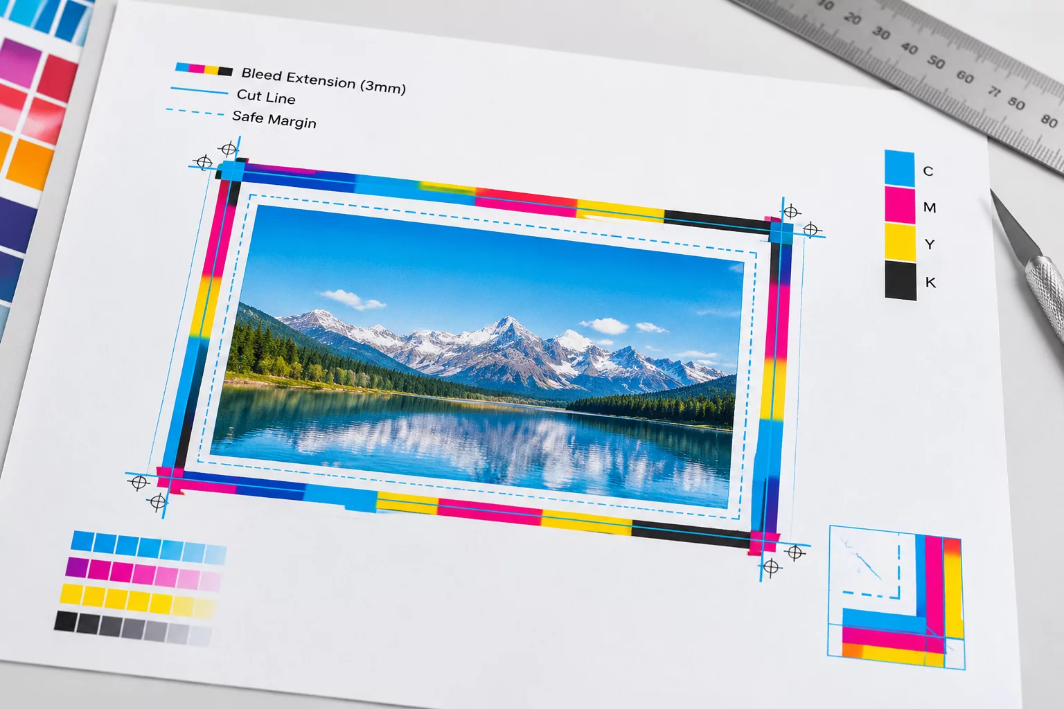
The Structural Difference Between Bleed and Margin
Print-and-cut workflows demand strict demarcation between artwork bleed that extends past the intended cut path and visible margin boundaries that guard vital design content. Confusing these two spatial tolerances frequently produces white flash on trimmed edges or unintentionally amputated borders.
A bleed extension serves purely as sacrificial printing space designed to absorb inevitable mechanical wander of blade cartridges or paper feed rollers. In contrast, visible margins define the optical breathing room inside the vector cut contour. When production setups attempt to substitute one for the other, slight feed skew immediately destroys peripheral symmetry.
Review Silhouette Studio Cut Boundary Setup
Compare your vector contour configuration against standard registration tests and blade drift models.
Boundary Coordinates and Physical Trim Tolerances
| Parameter | Observed Vector Coordinate | Physical Trim Result |
|---|---|---|
| Outer Bleed Overhang | +1.50 mm outward vector offset | Full color coverage without edge flash |
| Nominal Cutline Vector | 0.00 mm reference boundary | Exact blade carrier trajectory |
| Safe Inner Visual Margin | -2.00 mm inward clearance | Text and badge details intact |
| Mechanical Feed Drift Allowance | ±0.65 mm roller lateral variance | Absorbed completely by bleed zone |
| Corner Radius Arc Tolerance | R = 3.00 mm tangent fillet | Smooth cut continuity across corners |
Mechanical Drift Mechanics and Offset Calculations
Desktop digital cutters rely on optical registration sensors that read corner marks to calculate sheet orientation. Regardless of sensor calibration precision, pinch rollers exhibit micro-slip along the Y-axis as sheet stock travels back and forth. This mechanical reality introduces a baseline variance between 0.3 mm and 0.8 mm across standard letter or A4 media sheets.
To protect finished trim edges from exposed substrate base, background fills must project into the bleed zone. However, amateur layouts often extend entire graphic elements—such as bounding stroke lines or decorative frames—into the bleed. Because the blade cuts along the nominal boundary rather than the bleed edge, those decorative frames become lopsided and visually irregular.
- Extend only background textures and solid flood coats beyond the cutline by at least 1.5 millimeters.
- Retain all visible stroke borders and typographic elements at least 2.0 millimeters inside the cutline.
- Verify cut contours in software by toggling print preview lines separate from vector cut paths.
Separating these zones during file preparation eliminates guessing during blade setup. When the blade tracks along the nominal contour, minor mechanical drift lands safely inside homogeneous overprint rather than clipping delicate design elements.
Bleed exists to be destroyed by the blade; margins exist to protect what survives. Conflating the two guarantees visible edge defects.
Practical Margin and Bleed Clarifications
Automated bleed tools often clone pixels outwards or apply a rough pixel smear. While adequate for organic photography, vector labels with sharp geometric corners or delicate gradients will display distorted fringing along the trimmed rim.
A minimum inset of 2.0 to 2.5 mm from the vector cutline is recommended for small text. Anything tighter risks optical crowding or accidental clipping when sheet feed drift reaches peak tolerances.
Bleed extension belongs strictly to the print raster layer and is not processed by the cutter carriage. Plotter execution speed depends solely on vector cutline complexity, node counts, and blade acceleration settings.