Pre-Cut Visual Verification Checklist
Five-point optical and spatial inspection sequence to catch registration drift, bleed misalignments, and sensor glare prior to sending blade operations.
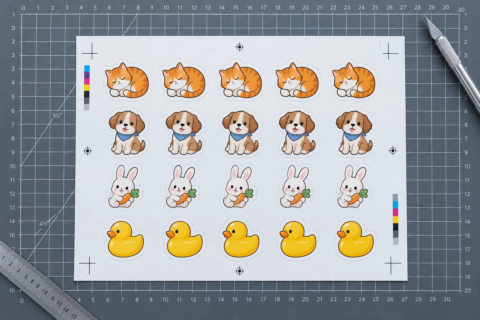
Systematic Optical Screening Before Tool Contact
Digital screen layouts frequently misrepresent the physical tolerances of desktop cutting plotters. Sending jobs straight from screen preview directly to the blade carriage without hands-on verification often destroys entire media sheets through offset drift, optical mark reader failure, or boundary clipping.
Print-to-cut registration relies on a rigid spatial contract between the optical sensors on the carriage and the printed graphic boundaries on the bed. A systematic pre-cut inspection isolates file setup errors from mechanical skew before the knife ever penetrates the vinyl backing or cardstock core.
Reviewing Print & Cut Layouts in Silhouette Studio
Examine exact screen ruler setups, optical mark thickness adjustments, and registration inset rules within software settings.
Critical Tolerance Thresholds and Resultant Defects
| Parameter | Observed Vector Coordinate | Physical Trim Result |
|---|---|---|
| Optical Mark Clear Space | 15.0 mm square exclusion zone | Zero optical misread rate |
| Safe Inset Margin Offset | +1.75 mm inside perimeter | Clean borders without text clipping |
| Outer Bleed Extension | +1.50 mm outside cut contour | Prevents white crescent fringes |
| Ganged Item Inter-Spacing | 3.0 mm minimum between parallel paths | Eliminates sheet tearing & web collapse |
| Pinch Roller Media Margin | 8.0 mm clear from sheet edge | Prevents roller skew and track slip |
Five Physical Validation Stages Before Blade Execution
Mechanical registration errors consistently originate from three distinct failure points: sheet loading distortion, software coordinate mismatches, and ambient lighting washouts over optical marks. Inspecting the physical media on the cutting mat immediately after printing reveals issues that digital software viewports cannot detect.
The operator inspects the printed sheet against three primary benchmarks: mark contrast, sheet planar flatness, and boundary offsets. A simple tactile run of the thumb across vinyl decals uncovers edge lifting that would catch a drag knife caster, while an eye loupe inspection validates that micro-text rests safely within the internal boundary perimeter.
- Verify that the square registration mark and crosshairs feature razor-sharp density with zero toner speckles or ink-jet bleeding inside the optical reader channel.
- Confirm full 1.5 mm color bleed beyond vector boundaries, guaranteeing that mechanical drift up to 0.75 mm will not expose blank paper slivers.
- Check clearance between cut paths and feed roller tracks to avoid tracking drift caused by blade pressure crossing roller indentations.
Maintaining this disciplined visual pass prior to sending cut jobs stabilizes repeat yield across multi-sheet runs. Even fractional adjustments caught at the inspection stage preserve expensive synthetic media, specialty vinyl, and plotter blade edges.
An uninspected sheet sent to the plotter is essentially an untested assumption about mechanical tolerance. Three seconds of deliberate optical verification prevents hours of material waste.
Pre-Cut Verification Clarifications
High ambient overhead lighting or direct LED task lamps frequently flood the sensor aperture with diffuse reflections, especially on glossy or holographic media. Shading the carriage with an index card during the reading cycle usually resolves mark detection failures immediately.
A minimum 1.5 mm bleed extension is recommended. While the machine motor may track within 0.5 mm, sheet skew, paper feed drag, and blade swivel hysteresis accumulate, requiring triple the single-axis theoretical tolerance.
Vector cut paths should always reside on a discrete, dedicated spot color or non-printing guide layer. Mixing strokes with raster art risks accidental printing of hairline boundaries or unwanted dual-contour processing during software RIP output.