Optical Mark Clearance and Sensor Safety Zones
Optical registration sensors calculate sheet position by scanning stark contrast transitions, meaning intrusion into hatched safety margins triggers instant registration drift or scan failures.
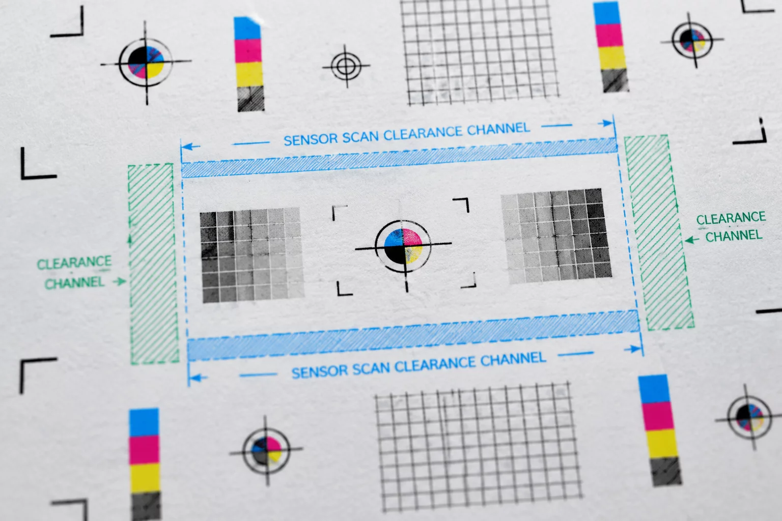
Why Optical Contrast Traps Compromise Registration Accuracy
Every automated desktop optical head registers coordinate baselines by projecting an infrared or visible wavelength emitter onto high-contrast printed geometries. When artwork bleeds or errant vector paths cross into this optical travel lane, the detector records premature luminance drops.
Plotter sensors move in predictable horizontal sweeping paths across the top square registration coordinate and along the lower vertical datum lines. These scan corridors require uninterrupted substrate contrast, which translates to unprinted matte media. A dark element placed even 1.2 mm away from an alignment mark can disrupt the hardware sampling array, skewing the coordinate grid across the entire sheet layout.
Reviewing Mark Boundary Rules
Verify hatched overlay grids and optical sensor sweep margins directly inside Silhouette Studio before initiating production runs.
Physical Clearance vs Registration Status Matrix
| Parameter | Observed Vector Coordinate | Physical Trim Result |
|---|---|---|
| Top-Left Square Isolation Margin | 8.5 mm absolute radial clearance | Zero Drift Detected |
| Corner Mark Encroachment Boundary | 3.1 mm proximity to target edge | 1.4 mm Angular Skew |
| Horizontal Sensor Scan Clearance | 12.0 mm clear optical sweep zone | Optimal Detection |
| Bottom Corner Return Axis Barrier | 4.0 mm bleed into hatched grid | Registration Sensor Abort |
| Laminate Overlap Over Optical Mark | Specular reflection threshold exceeded | Intermittent Read Failure |
Spatial Drift Analysis Across Optical Transit Lanes
Optical registration sensors do not read coordinate targets as static camera snapshots. Instead, a photodiode scans continuously as the carriage moves laterally, sampling light reflection ratios at microsecond intervals. The system expects a sudden transition from neutral high reflectance to absolute dark absorbency exactly when crossing the printed registration square.
Whenever printed decorative patterns or rich vector graphics reside inside this approach vector, the photodiode measures false contrast shifts. This leads the internal firmware to miscalculate mark boundaries by several steps, resulting in linear registration drift across all cut coordinates downstream.
- Keep a minimum 6.0 mm clear safety zone around all square and angle registration geometry.
- Avoid laminating over optical targets with high-gloss films that produce specular lens glare.
- Deactivate vector outlines and bleed geometries located inside hatched software safety grids.
Maintaining strict separation between graphical cut items and sensor corridors guarantees reliable mechanical registration. By respecting these boundary zones, print-and-cut workflows maintain precise vector tolerances without recurring manual recalibration runs.
The optical eye requires complete contrast silence before detecting the registration mark. Encroaching into this zone introduces coordinate inaccuracies across the entire cut layout.
Frequently Asked Questions
No. Any printed ink layer inside the hatched region introduces unwanted optical noise. The photodiode relies on pristine media contrast to determine threshold coordinates accurately.
Specular reflection bouncing off high-gloss laminates can blind the optical sensor during its pass. Trimming laminate sheets to avoid covering the registration targets eliminates glare issues.
We recommend maintaining at least 5.0 mm to 6.5 mm between cutline coordinates and the inner edge of any mark boundary to prevent blade pressure from warping the target paper plane.