Establishing Safe Inset Margins for Vector Cutlines
Calculating structural internal tolerances, preventing perimeter text clipping, and neutralizing feed drift on desktop and production cutters.
Why Vector Contours Shift Under Sheet Transport
Every desktop cutting plotter and roll-fed production unit operates with microscopic mechanical variance during feed cycles. Even with optical sensor registration marks accurately read, pinch roller friction, minor sheet skew, and blade drag introduce positional shifts between 0.25 mm and 1.2 mm across a single media sheet.
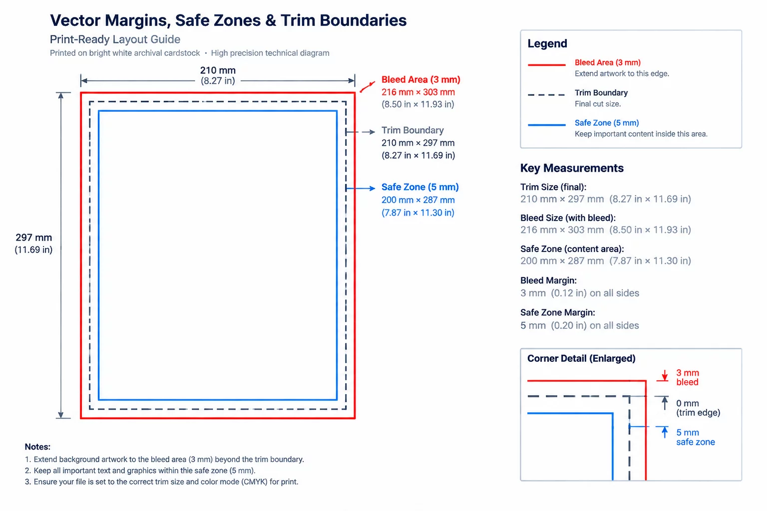
Designing artwork boundaries directly adjacent to the vector cutline creates a zero-tolerance hazard. When the carriage executes the cut path along an unbuffered edge, any microscopic lateral skew exposes an unsightly white sliver or lops off essential design elements. Establishing an intentional safe inset margin inside the vector cutline guarantees that text, fine linework, and foreground emblems remain intact regardless of mechanical deviation.
Browse Print-to-Cut Case Studies
Review documented inspections examining how unbuffered boundaries lead to asymmetric margins and perimeter clipping.
Empirical Coordinate Tolerances for Vector Insets
| Parameter | Observed Vector Coordinate | Physical Trim Result |
|---|---|---|
| Typography Inset Buffer | ≥ 1.50 mm (4.25 pt) inward from cut path | Zero Letterform Cropping |
| Fine Detail & Icon Closeness | ≥ 1.20 mm (3.40 pt) inward from cut path | Safe from Edge Delamination |
| Full-Bleed Exterior Extension | +1.75 mm to +2.00 mm outward from cut path | Complete Color Run, No Halo |
| Optical Sensor Clearance Gap | ≥ 15.00 mm clearance around square mark | Clean Optical Scan Pass |
| Multi-Up Gang Sheet Spacing | ≥ 3.00 mm separation between adjacent cuts | Rigid Carrier Webbing Intact |
Geometric Inset Formulas for Die-Cut & Kiss-Cut Workflows
When drafting vector cutting contours inside vector graphics environments such as Silhouette Studio, Illustrator, or CorelDRAW, operators frequently confuse the visible sticker frame with the blade trajectory. A safe vector layout requires three distinct spatial tiers: the bleed perimeter on the exterior, the cutting contour in the center, and the safe inset boundary on the interior.
For die-cut stickers penetrating both vinyl and backing liner, mechanical stresses increase. High downforce causes slight compression of the carrier paper, shifting coordinates progressively toward the bottom half of the sheet. In kiss-cut sheets, blade friction pulls elastomeric face film laterally, especially when turning sharp 90-degree vector nodes.
- Generate an internal offset of at least 1.5 mm for all essential typographic and brand elements.
- Avoid acute vector angles below 30 degrees that pinch material and snag during blade turns.
- Group the artwork and cut contour on locked discrete layers before calculating alignment coordinates.
Adhering to these structural inset rules guarantees consistent visual margins across production batches. Whether cutting twenty labels or two hundred gang-sheet elements, proper inset geometry absorbs transport drift without compromising the artwork integrity.
A cutline placed flush against color edges guarantees an accidental white sliver whenever mechanical sheet feed deviates by even a fraction of a millimeter.
Frequently Asked Inset Questions
A bleed margin extends background imagery outward beyond the cut contour to eliminate unprinted borders, whereas an inset margin pulls critical graphic elements inward from the cut contour to prevent mechanical clipping.
For typography smaller than 9 pt, keep at least 1.5 mm of clearance between glyph stems and the blade path. On dense or heavy-grip media, expanding that buffer to 2.0 mm is advised.
As the sheet feeds through the pinch rollers, micro-slippage accumulates across long travel distances. Without intermediate registration points, lower items exhibit greater coordinate variance than those near the top optical marks.