Asymmetrical Corner Radii on Trim Lines
Evaluating geometric distortion and optical imbalance when unequal corner fillets meet mechanical blade tangential rotation on rounded rectangular cut paths.
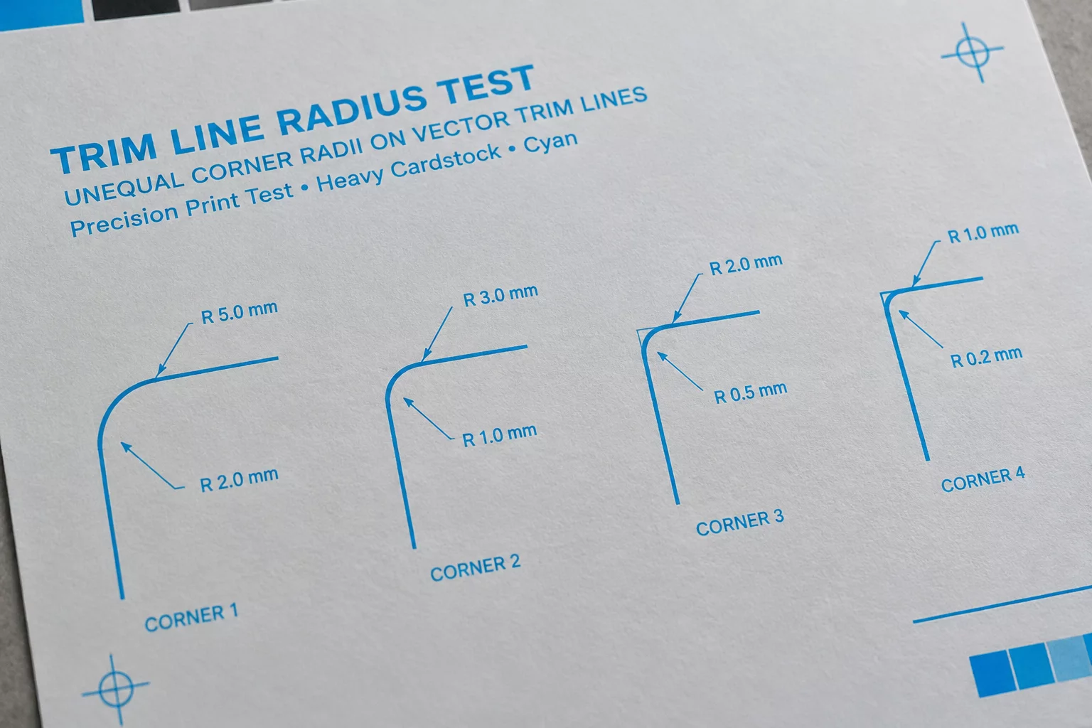
The Visual Tension of Mismatched Fillets
When a rounded rectangular label features uneven corner radii—such as tight top corners paired with sweeping bottom arcs—the cutting plotter encounters drastic shifts in tangential blade acceleration.
Digital previewers render mathematical Bézier curves effortlessly, yet drag knives and tangential blades experience fluctuating mechanical resistance. On asymmetrical trim contours, slight registration offsets amplify visual asymmetry, turning deliberate styling into an apparent cutting error.
Reviewing Inset Margins
Discover how safe inset margins prevent boundary clipping on asymmetrical vector contours.
Coordinate Comparison & Mechanical Variance
| Parameter | Observed Vector Coordinate | Physical Trim Result |
|---|---|---|
| Top-Left Arc Radius | r = 2.50 mm (90° Arc) | Nominal ±0.05 mm |
| Bottom-Right Arc Radius | r = 6.00 mm (Compound Spline) | +0.32 mm Blade Drag Offset |
| Printed Perimeter Bleed | 1.20 mm Uniform Offset | Incomplete Lower Arc Coverage |
| Blade Lead-In Point | Midpoint of 6.00 mm Arc | Micro-Tear at Vector Junction |
| Optical Margin Inset | 3.00 mm from Cut Line | Visual Weight Imbalance |
Why Asymmetrical Curves Challenge Blade Tracking
Mechanical plotters rely on swivel drag knives that rotate around their physical caster offset. When transitioning abruptly from a tight 2.5 mm radius to an extended 6.0 mm curve, the blade's pivot angle shifts at differing velocities across identical feed speeds.
The asymmetry also confuses pre-flight automated bleed generators. Standard offset routines generate parallel paths, but manual spline edits frequently introduce subtle flat spots along wider arcs, causing the printed ink edge to decouple from the cut trajectory.
- Place initial blade plunge points along straight segments rather than complex or variable corner arcs.
- Maintain a constant ratio between bleed clearance and varying corner radii to prevent exposed cardstock edges.
- Normalize tangential acceleration curves in cutting software when mixing tight fillets with broad sweeps.
Thorough inspection under coordinate magnification shows that compensating for asymmetrical fillets requires decoupling artwork offset layers from unified mathematical expansion.
An asymmetrical cut path demands deliberate mechanical compensation; assuming uniform blade drag across mismatched radii inevitably reveals white paper core along the wider arc.
Asymmetrical Vector Cutline Questions
A larger radius spreads the tangential path across more linear travel, giving micro-feed slippage and drag blade caster inertia more distance to deviate from the true vector coordinate.
Always position the cut start and end point on the longest straight edge. Starting within an arc forces the blade to plunge and pivot simultaneously, creating visible entry gouges.
Instead of a generic stroke-based bleed, apply vector offset curves that match each specific fillet radius independently so that margin thickness remains visually harmonious.