CALIBRATION & TOLERANCE.

Review the Space Between Print and Cut

Explore cases about printed artwork, cut boundaries, margins, repeated labels, internal openings, and final-piece expectations.

FIELDBOOK ARCHITECTURE.

Print/Cut Review Sheets by Question

Every review asks: “What needs to remain visible, printable, and cuttable around this design?”

CASE INSPECTION 08.

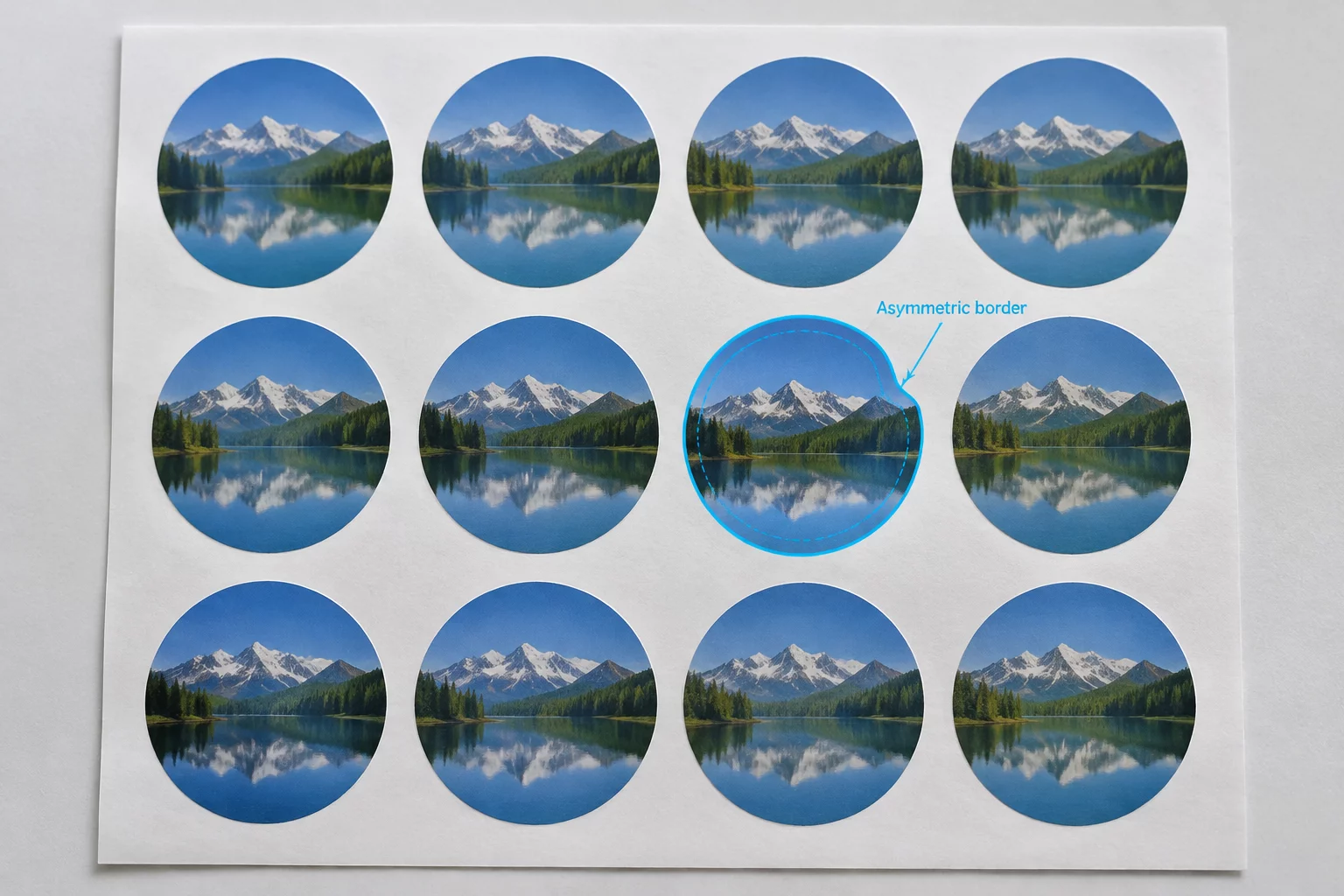
The Sticker Looked Centered Until the Cut Was Added

An empirical teardown comparing optical mass alignment against mechanical coordinate paths across two physical sticker runs. Examining why graphic symmetry in design software drifts when registration blades engage the substrate.

PROTOTYPE A OPTICAL CENTERING

Centroid Offset on Graphic Weight

The design was optically aligned to the visual center of gravity rather than the geometric bounding box. While visually harmonious on screen, the physical cut contour yielded asymmetric border margins ranging from 1.2 mm on the left to 2.8 mm on the trailing edge.

Bounding Reference: Optical Center of Mass
Trim Variance: +1.6 mm Lateral Bias
Visual Perimeter: Non-Uniform Edge Reveal
PROTOTYPE B MECHANICAL CENTERING

Equidistant Coordinate Inset

The vector cutline was calculated as an absolute mathematical offset from the outer raster bounding coordinates. The white bleed margin measured precisely 2.0 mm on all axes, yet the perceived graphic motif appears pulled toward the upper quadrant.

Bounding Reference: Geometric Hull Extents
Trim Variance: 0.0 mm Mechanical Drift
Visual Perimeter: Uniform 2.0 mm Perimeter
DIAGNOSTIC LAYERS.

Interactive Stack Breakdown

Select a physical inspection layer below to isolate the spatial interaction between printed pixels and plotter knife paths.

LAYER 01 BASE PRINT PASS

Printed Artwork Boundary

The raster image is deposited with full saturation onto adhesive substrate. Without trim reference paths displayed, the human eye calculates balance relative to the surrounding empty paper background, creating a cognitive illusion of equilibrium.

Substrate Bleed Overhang: 1.5 mm Exterior
Artwork Perimeter Area: 74.2 mm x 72.8 mm
LAYER 02 VECTOR CONTOUR

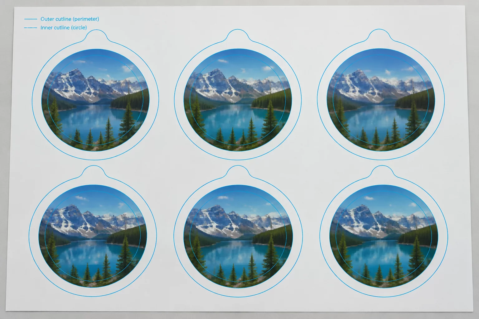
Offset Cut Contour Vector

A 0.05 pt pure magenta stroke defining Cartesian node data for the plotter carriage. The path ignores ink density variations, applying identical radius rounding across all outer corner nodes.

Path Coordinate Count: 38 Vector Nodes
Blade Offset Distance: +2.0 mm Standard Offset
LAYER 03 SAFETY BOUNDARY

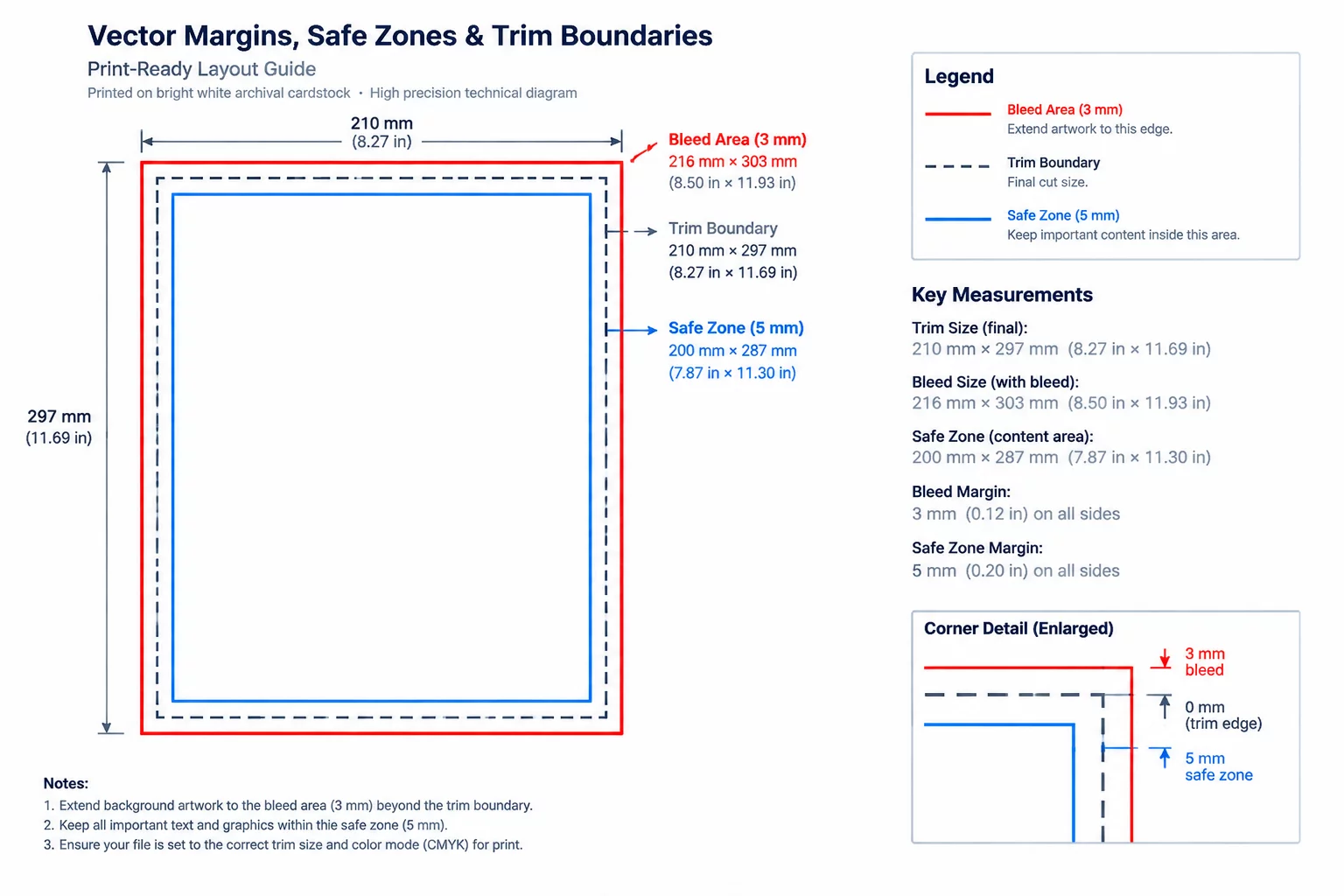
Visible Perimeter Margin

The unprinted carrier band between the ink edge and the trim line. Any discrepancy between graphic density center and geometric centerline generates a noticeable wedge effect along this border.

Observed Border Delta: 1.2 mm to 2.8 mm
Registration Drift Buffer: 0.75 mm Maximum
LAYER 04 DIE CUT TERMINAL

Finished Cut Sticker Outcome

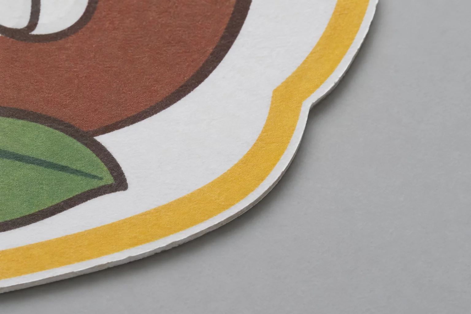
Peeling the die-cut peel-off reveals the mechanical truth: while technically in spec according to cutting software, the emblem presents an off-balance slant to end users unless vector compensations are tuned.

Final Verification: Requires +0.8 mm Manual Bias
Physical Edge Integrity: Clean 90° Substrate Shear
INSPECTION SPECIFICATIONS.

PRE-PRESS ACCURACY OUTCOMES

Standardized technical advantages verified across vector contour calibration and optical print-to-cut alignment inspection.

Predictable Edge Margins

Establishes definitive boundary offsets before exporting cutting jobs, securing blade path clearance against material edges.

White Sliver Eradication

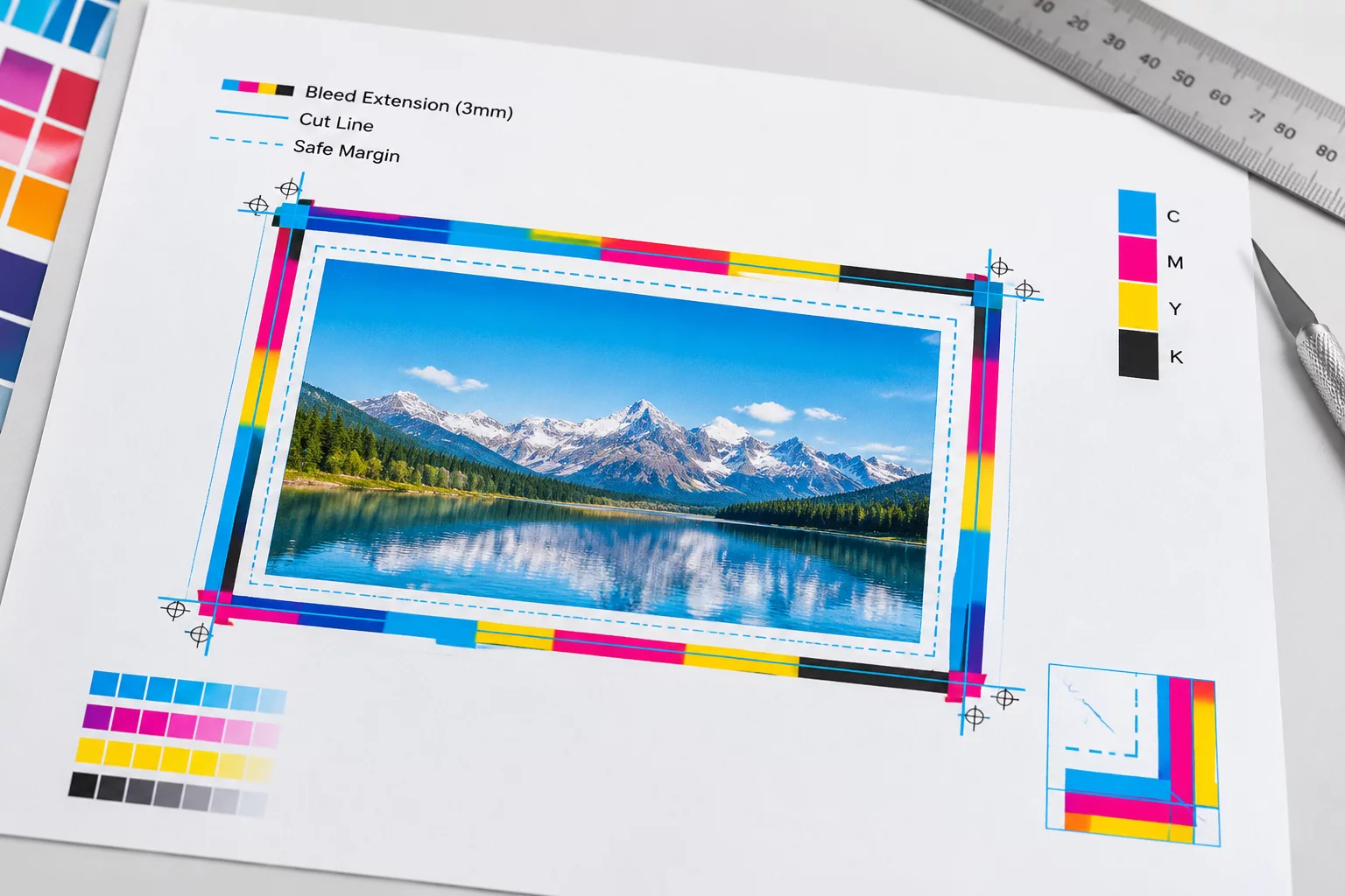
Eliminates accidental raw substrate exposure through calibrated outer bleed extensions counteracting physical blade drift.

Preserved Counter Openings

Protects internal cutouts and intricate geometric voids, preventing bridge webbing collapse on complex die shapes.

Uniform Perimeter Spacing

Standardizes inter-unit gutters and stepped matrix relief across gang sheets, maintaining consistent tension during peeling.

Verified Mark Clearance

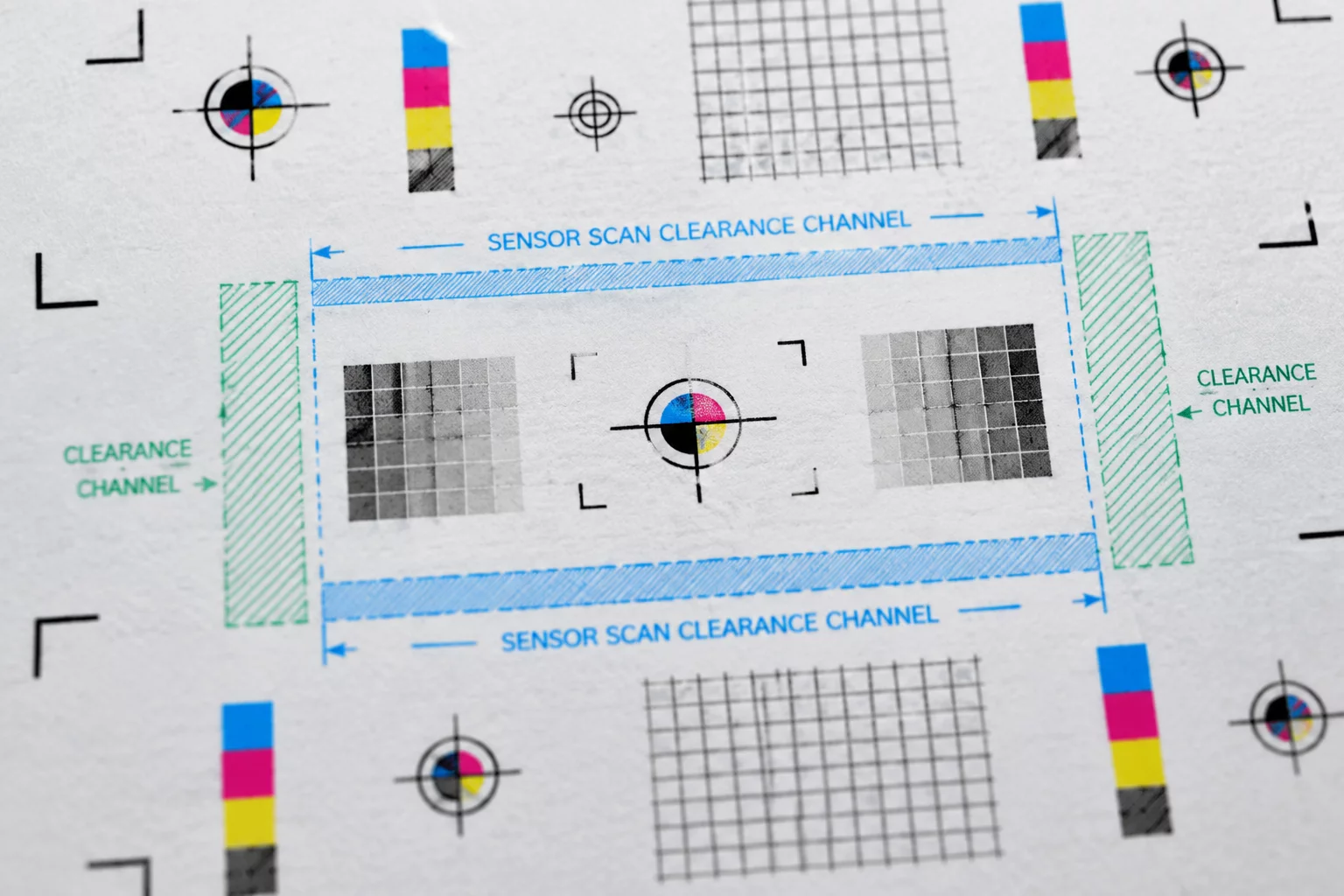
Preserves designated safety zones around optical fiducial marks, avoiding optical sensor misreads during batch registration.

Vector-Graphic Separation

Maintains strict hierarchy between vector strokes and artwork raster pixels to avert prepress rendering conflicts.

ENVIRONMENT MATRIX.

Production Tools & Inspection Environments

Controlled baseline data gathered across desktop plotters, native software revisions, and file conversion parsers. Every benchmark measures coordinate drift under standardized optical illumination.

Engine v5.0.539 Build Target: Dedicated Print & Cut

Silhouette Studio V5 Engine Diagnostics

The v5.0.539 architecture isolates vector contours from raster print passes. When operating through the dedicated Print and Cut panel, margin clipping thresholds default to conservative bounding boxes, triggering unannounced auto-offsets on custom sheet sizes.

Engine Build: v5.0.539 Stable
Buffer Boundary: Zero-Bleed Safe
Panel Handling: Direct Coordinate Pass
Render Resolution: 1200 DPI Vector Buffer

Observed Anomaly Profile

  • Pre-print bounding box expansion when switching from Letter to custom dimensions.
  • Layer stacking suppression in multi-color registrations without flattened groups.
  • Vector cutline scaling shifts during non-standard DPI exports to PDF rasterizers.
CASE AUDITS.

Visual Cutline Case Studies

Independent visual verifications dissecting vector cutline coordinates, perimeter offsets, and registration drift at millimeter precision.

Need full laboratory logs across all test layouts?EXPLORE COMPLETE ARCHIVE
CALIBRATION PROTOCOLS.

Essential Margin & Cutline Manuals

Standardized offset coordinate sheets, sensor safe zones, and vector boundary parameters calibrated for rotary, flatbed, and digital plotter production runs.

TECHNICAL REVIEW BOARD.

Pre-Press Review Specialists Behind the Fieldbook

Independent calibration practitioners dedicated to diagnostic testing of vector paths, cutting plotter registration, and micro-drift across physical production substrates.

Sarah Lin - Lead Print and Cut Production Engineer 11 YRS CALIBRATION

Sarah Lin

Lead Print/Cut Production Engineer

Specializes in digital die-making protocols and multi-sensor optical registration alignment. Coordinates boundary tolerance verifications and repeatable registration mark benchmarks.

Core Focus: Optical Sensor Zones & Die Tolerances
Marcus Vance - Vector Path and Pre-Press Specialist 8 YRS PATH AUDITING

Marcus Vance

Vector Path & Pre-Press Specialist

Focuses on diagnosing plotter coordinate offsets, Bezier vertex density, and nested sheet geometries. Analyzes how automated curve algorithms introduce micro-clipping along trim edges.

Core Focus: Vector Nesting & Node Compression
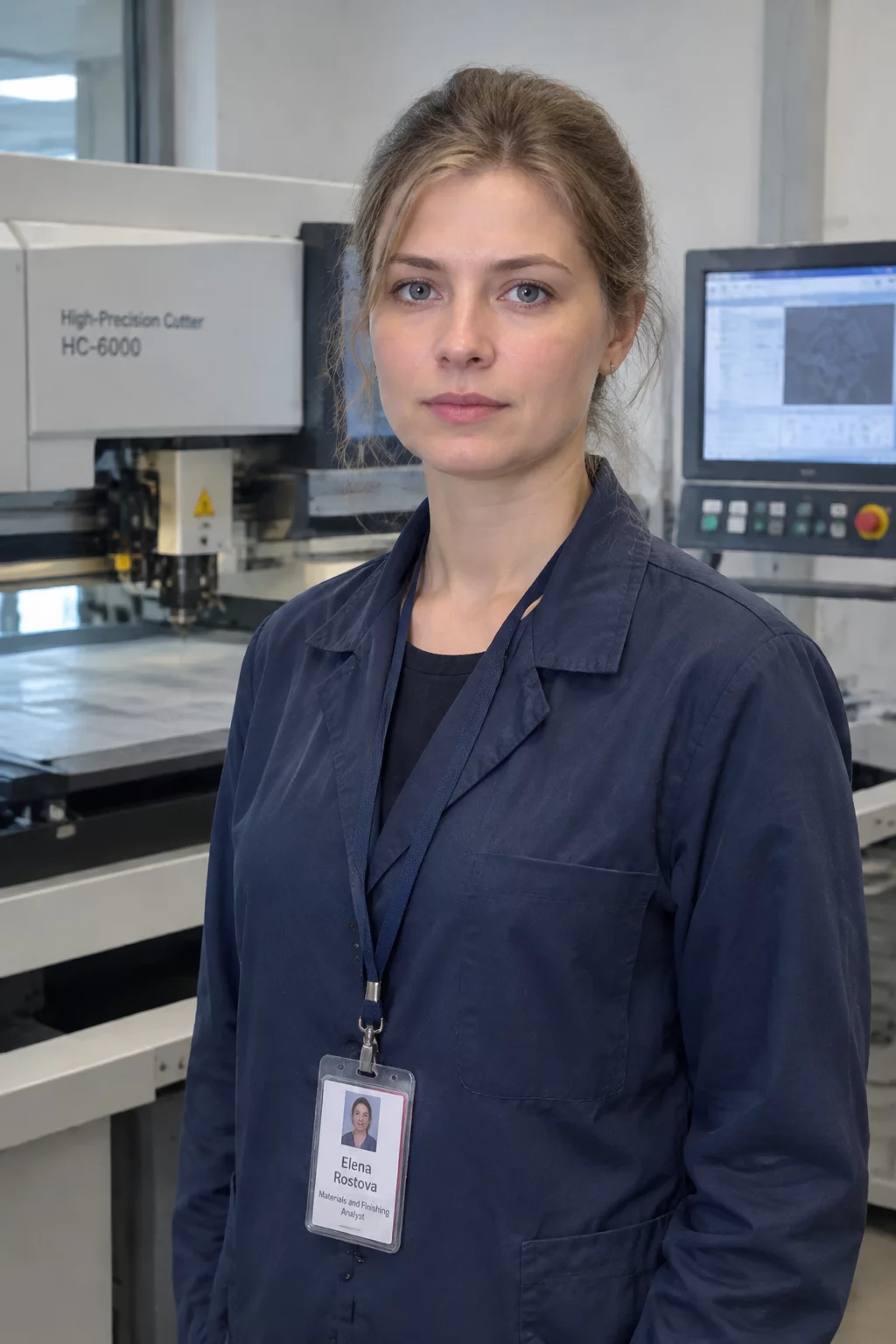
Elena Rostova - Material Finishing and Blade Offset Analyst 9 YRS MEDIA TESTING

Elena Rostova

Material Finishing & Blade Offset Analyst

Examines media drag resistance, tangential blade swivel wear, and linear tension skew across synthetic films and heavy coated cover stock during high-volume cut passes.

Core Focus: Blade Wear Dynamics & Media Drag
28 YRS Cumulative Production Experience
0.05 MM Cutline Inspection Precision
140+ Substrate Calibrations Reviewed
100% Independent Studio Audits
EXPERT COORDINATE AUDIT.

Schedule a Precision Layout Review

Direct one-on-one spatial diagnostic session with print-to-cut technicians. We examine your vector cut paths, registration target offsets, bleed limits, and structural clearance in real time.

Live CAD / vector path alignment inspection
Optical registration sensor safety margin diagnosis
Gang-sheet spacing and blade draft compensation check